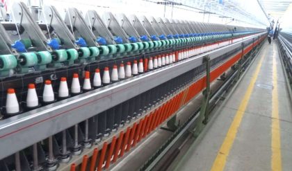
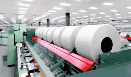
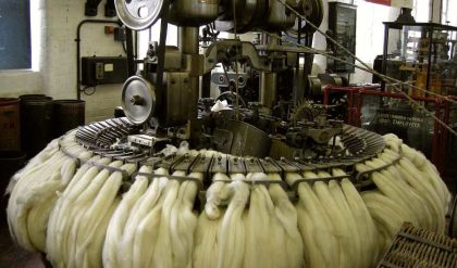
About 20% of production costs in a spinning mill fall under the heading “energy”, and of these costs about two thirds are incurred in the ring spinning section. For example, in a ring spinning mill with 25,000 spindles and an operating time of 7000 hours per year, a saving of 10% on an annual power bill of $1 million will bring very interesting financial returns.
Power supplied to the ring spinning machine is absorbed by
The spindles – 65 to 70%
The drafting arrangement – 25%
The ring rail – 5 to 10%
However, technological problems associated with machine drive are still more serious than economic ones. Extreme yarn tension variations occur during winding of a cop and it would be useful to reduce these tension variations by adjusting spindle speed. Fig.1 shows the ring rail movement, yarn tension and ends down occurred in ring spinning operation.

During winding of a cop layer, yarn tension rises as the ring rail moves upwards, i.e. from the larger to the smaller winding diameter. The tension increase is significant, e.g. from 24 to 40 cN, and there is a corresponding effect on the number of end breaks.
An investigation shows that most end breaks occur during raising of the ring rail in the upper region. In order to hold yarn tension and the end break rate constant, spindle speed should be reduced during raising of the ring rail (speed variation within the layer).
A similar problem arises in relation to the package build taken as whole. At the start of winding of a cop the balloon is very large, but at the finish it is relatively small. Yarn tension changes accordingly. In this case also adjustment is needed via the spindle revolutions (control of the basic spindle speed).
Previously, both speed adjustments could be carried out with controlled operation of a commutator motor. Today, usually only basic spindle revolutions are adjusted by variators, direct current motors or frequency drives.
The control programme should include at least a starting phase (for avoiding end breaks during starting), a preliminary stage (for winding of the main body of the cop). An end stage is often provided for winding of the uppermost portion of the cop; this can be identical to the preliminary stage.
Motors used in Practice
· Motors that are have been used in ring spinning mills are as follows,
· Alternating current with short-circuited rotors (squirrel-cage motors)
· Squirrel cage motors with star delta starters
· Squirrel cage motors with variators
· Pole changing squirrel cage motors
· Asynchronous motors with current controlled frequency; converters
· Alternating current, shunt wound commutator motors
· Direct Current motors.
Squirrel cage motors with variators
In this case, speed adjustment is not carried out at the motor itself, but by means of adjustable grooved discs (Fig.2) in the belt drive, similar to a cone transmission. However, whereas in the cone transmission a required change of diameter relationships is effected by shifting the belt axially of the cone drum pair, in the variators the change in diameter is effected by shifting the belt radially on two v-pulleys, each made up by a respective pair of conically-faced disc movable towards and away from each other. If the discs of one pulley are moved apart and those of the other pulley are moved together, the drive belt passes onto a larger diameter of the one pulley, and a smaller diameter of the other.
The winding process
The ring rail has to perform two movements; a continuous up and down movement in order to lay one main and one cross winding (traverse cycle); and gradual raising in small steps after each layer movement in order to fill the cop.
Each of the movements has a very undesirable effect on the spinning conditions. In particular, the size of the balloon and the winding diameter on the cop are subjected to continual change. This leads directly to considerable tension variations during winding.
To mitigate this effect, the balloon control rings and the thread guides perform the same movements as the ring rail, but with shorter stroke as regards both traverse and lift.
In the winding of a layer, the ring rail is moved slowly but with increasing speed in the upward direction and quickly but with decreasing speed downwards. This gives a ratio between the length of yarn in the main and cross windings of about 2:1. The total length of a complete layer should not be greater than 5 m to facilitate unwinding. The traverse stroke of the ring rail is ideal when it is about 15-18% greater than the ring diameter.


