It has already been mentioned that the ring rail is not moved uniformly. Its speed increases during upward movement and falls during downward movement. At the tip of each layer it is higher than at the base of the layer that is the ring rail does not dwell as long at the tip as it does at the base – less material is wound, the layer is thinner at the tip.
If it is assumed by way of example that the ring rail is moving twice as fast at the top of its strokes as at the bottom of the stroke, the first layer would be half as thick at the top as at the bottom, i.e. b1/2instead b1.
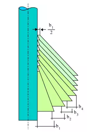
The first layer would correspond to a trapezium with the side b1 at the bottom and the side b1/2 at the top. This is followed by the deposition of the second layer. Owing to the lifting of the ring rail, the upper portion of the new layer would again be deposited on the bare tube.
The average diameter at the top would be the same as that of the first layer, and the volume, and hence the thickness, would also be the same, that is b1/2.
Each newly deposited layer will have this thickness of b1/2 at the top. At the bottom, however, the diameter is increasing continually, the layer thicknesses decline from b1 to b2 to b3 to b4… Accordingly, continually narrowing trapezia are produced.
At some stage, the trapezium will become a parallelogram, i.e. the lower side will be the same size as the upper side: both will be b1/2. Since all other winding conditions now remain the same, no further variation can now arise in the layering.
One conical layer will be laid upon the other until the cop if full, that is when the cylindrical portion of the cop is formed.
The gearing change wheel has little influence on this sequence of events. If too many teeth are inserted, the final condition of constant conical layers will be reached too soon and the cop will be too thin. It will be too thick if the ring rail is lifted too slowly.
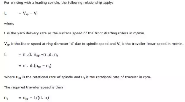
The winding Principle
As in the case of the roving frame, two components with different speeds must be used in order to enable winding to occur. One assembly is the spindle, the other is the traveller representing the remnant of the flyer.
Also, the speed difference must be equal over time to the delivery length at the front cylinder. In the roving frame, each assembly has its own regulated drive. In the ring spinning frame this is true only for the spindle. The traveller is dragged by the spindle acting through the yarn.
The speed of the traveller required to give a predetermined speed difference arises through more or less strong braking of the traveller on the running surface of the ring. Influence can be exerted on this process by way of the mass of the traveller.