Texturing processes are essentially concerned with introducing bulkiness into continuous-Filament? (CF) yarns. This means CF yarns generally are the starting material for the texturing processes. However, some melt-spun CF yarns can be textured during their extrusion by special modifications to the melt spinning. Before describing the various principles of texturing it is useful to first consider what is meant technically by continuous-Filament? yarns and outline the commonly used raw materials converted into such yarns.
Definition of CF Yarns
There are various published definitions of a continuous Filament? yarn . The Textile Institute’s publication “Textiles Terms & Definitions” [1] refers to a Filament?as a fibre of indefinite length[1]. A continuous Filament? yarn can then be defined as “A yarn composed of one or more filaments of length/lengths equal to the specified yarn length”. Thus, if we have a bobbin with, say, a 100m of CF yarn all the filaments would be 100m in length.
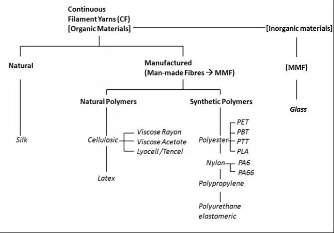
Fig.1 Classification of Continuous Filament? Yarns
Classification of CF Yarns
Similarly to spun yarns, CF yarns may be classed as natural or manufactured yarns (i.e. man-made filaments –mmf). However, as Fig.1 shows, the only natural Filament?yarn is silk, but the mmf category can be divided in CF yarns made from natural and synthetic polymers, and from inorganic mineral materials. The chart lists different materials within these groups that are widely used in textile applications. (See Material Section for Technical Details)
In the classification of CF yarns three further points must be considered. Firstly, when a CF yarn is in the form of one Filament? it is referred to as a mono-Filament? CF yarn (or in short a monofilament), and when of several filaments, a multi-Filament? CF yarn (or just a multifilament). The second point is that during production of organic Filament? yarns, the polymer chains of the filaments may be brought to a relatively high degree of parallelism with Filament? axes by mechanical attenuating action, called drawing. The filaments are loosely termed fully drawn or fully oriented, and the CF yarn is then called a fully drawn /fully oriented yarn (DFY/FOY). If the filaments are made to have a low degree of parallelism the resulting yarn is then classed as a partially oriented yarn or POY.
The third point is that FDY/FOY are straight along their lengths and have little significant bulkiness. In this form they are called flat or untextured yarns, meaning that they are inherently smooth, have no loftiness, no stretch under low applied forces (excepting for elastomers), and are lustrous in appearance – unless modified by additives. In this form they have a limited range of applications. It is the conversion of this flat form into one that show bulkiness that is termed texturing, and hence CF textured yarns. The texture can be visualised as being either of two forms; a waveform crimpiness along the lengths of the filaments or a profusion of loops along them. The idea of texturising CF yarns is to modify the physical properties of the filaments so that the CF yarns can be more opaque, have good bulk and stretch at low tension, thereby imbuing similar fabric characteristics as staple yarns such as increased thickness and cover, softness and warmth, stretch, suitable water vapour permeability and moisture transport (i.e. breathability).
The Texturing Processes
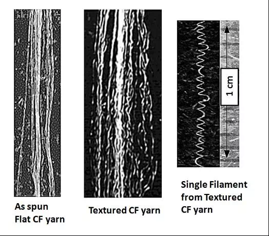
In the texturing processes, a CF yarn has to undergo a major change in its physical form, by becoming crimped, coiled or looped along its lengths. See Fig.2. Only multifilament CF yarns are suitable for texturing. There are various methods that may be used to produce textured CF yarns. Most are only applicable to thermoplastic CF yarns as they involve heating the filaments while effecting the textured profile, then cooling to retain it in the filaments. From the technical perspective, the ones most commonly referred to are [70]:
· Knife Edge: where the Filament? yarn is heated and pulled across a knife at an acute angle. When the yarn is cooled and released it retains a spring or curled ribbon appearance, i.e. the profile is heat-set.
· Stuffer Box: here the filaments pass through a heated box, but are fed into it faster than their removal rate – i.e. an overfeed. This forces them to adopt a random wavy crimped pattern while heated; subsequent cooling sets their textured form.
· Air Jet: with this method overfeeding of filaments at high speed into a chamber is also employed, but instead of using heat to facilitate the texture profile, compressed air is blown into the chamber and this causes the loose lengths of the filaments in the yarn to spread apart and form entangled random loops. The entanglement retains the texture of random loops
· False Twist?: in this method the CF yarns are twisted and heated simultaneously, and then untwisted when cold, thereby loosely retaining the heat-set helical shape of the Twist?.
· Knit-De-Knit: here Filament? yarns are knitted into a narrow diameter tube and heat-set (i.e. heated and then cooled). The yarns are then de-knitted, giving them a wavy configuration.
· Bicomponent Process: with this method the texture is obtained by twisting to together filaments of high and low potential shrinkage. Subjecting the resulting yarn to washing or steaming results in the differential shrinkage of the filaments to form the ulked profile.
Fig.2 Flat and Textured CF Yarns
Of the above methods briefly described, the more widely used are false-Twist?texturing and air-jet texturing, the former being the dominant.
False Twist? Texturing
To describe the basics of the false Twist? texturing process it is necessary to first consider the meaning of real Twist? and the term false Twist?, and how the latter is produced.
Real Twist?
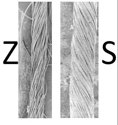
When Twist? is inserted into a CF yarn, starting at its free end, the filaments adopt a helical shape (or spiral) which may be a clockwise or counter clockwise spiral, in accordance with the direction of rotation of the twisting device. With the clockwise spiral, the inclination of the helix mirrors the inclination in the letter Z, and the Twist? is called Z-Twist?. Similarly with counter clockwise the Twist? is referred to as S-Twist?; see. Fig.3. Importantly, after the action of twisting the inserted Twist? remains in the yarn[1].
Fig.3 Z – and S-twisted yarns
False Twist?
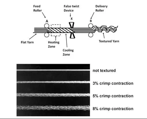
If a twisting device, through which the yarn passes, is located so that the Z-twisting action (the clockwise torque) occurs on the yarn as the yarn is made to run into the device, and as the yarn runs out of the device the S-twisting action (the counter clockwise torque) occurs, then no Twist? will remain in the yarn, since the Z-Twist? will be removed by the counter clockwise torque. This means that within a short time of starting the twisting process, Z-Twist? will be seen in the yarn as it runs into the twisting device, but no Twist? will be present as it leaves. This is the false-twisting action as Fig 4 illustrates.
The figure depicts the situation where a CF yarn, nipped by two pairs of rollers at positions A and B is driven at a linear speed of Vd m/min. The yarn is also constantly being twisted at the location X by some device, as its length moves through the distance AB. If the twisting device is rotating at Ns rpm in the direction shown, then when viewed from A, along the length AX, it will appear to be turning clockwise. Viewed from B, along the length BX, it will appear to turning counter clockwise. The one device will therefore at any instant in time effectively Twist? in the clockwise direction, the yarn length present within the zone AX, inserting Z-Twist?. Simultaneously, the yarn length present within the zone XB will receive a counter clockwise torque, inserting S-Twist?. In a very short time, the Z-Twist? in the yarn length present in AX will increase to a constant value equal to Vd / Ns turns per metre. In zone XB, the S-Twist? present in the yarn length passing through the zone will increase to a maximum value and then decrease to zero. This is because each length of yarn moving from zone AX into zone XB will become untwisted by the counter clockwise torque present in zone XB. If the yarn were to be heated above the Tg [1] of the polymer while it is being Z-twisted in zone AX, Fig.5, and then cooled before being untwisted in zone XB, the spiral shape of the individual filaments comprising the CF yarn would be retained, but the filaments would become free of the Twist? compaction resulting a false-Twist? textured yarn; bulky with considerable stretch (elongation or Twist? usually intended to be cut or stretch-broken for use in staple fibre or top form.”>Tow?.”>Crimp? contraction at low applied force) depending on the level of false twisting. Since false-Twist? texturing requires the filaments to be initially heated above their Tg, the process is only suitable for thermoplastic polymeric filaments. For more in-depth study of the principles of false-Twist? texturing the reader is referred to [70]
Fig.4 Illustration of the False Twisting Action
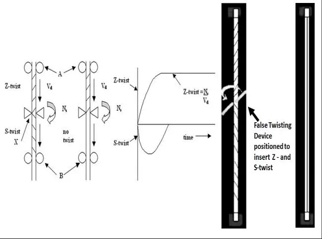
Fig.5 Illustration of False-Twist? Texturing Principle
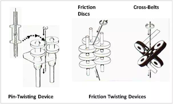
During the earlier years of false-Twist? texturing FDY/FOY yarns were texturised using a rotating pin as the false-Twist? device. As Fig 6 illustrates, the pin twister is a hollow spindle with a central pin positioned across the tubular interior. The flat CF yarn passes down the tube and around the pin. The rotation of the pin is effected by a driven disc assembly.
By including a mechanical drawing stage(i.e. a hot-draw zone) before the heating/twisting/cooling zone, POY yarns could then be utilised, giving better process economics and product variety in terms of bulk and stretch, depending on the pre-drawing; the yarn being referred to as a draw-textured yarn or DTY. In addition, the pin-twister may be replaced with a friction-twisting device [71]. See Fig.6. This is an assembly of overlapping discs which enables the CF yarn to be directly friction twisted, replacing the need for the hollow spindle. Another type of friction twisting device used is based on driven cross-belts. These latter devices enable higher twisting speeds, 20 x106 rpm as opposed to 8 x10⁵ for pin twisting, resulting in production rates of up to 12000m/min, depending on polymer and yarn count.
Fig.6 Illustrations of False-Twisting Devices
The DTYs are considered to be highly stretchable yarns, because in addition to the recoverable part of the intrinsic extension from their melt spun structure, there is the added extension attributable to the Twist? usually intended to be cut or stretch-broken for use in staple fibre or top form.”>Tow?.”>Crimp? imparted by the texturing process. Highly stretchable yarns can be made by applying high levels of false-Twist?, resulting in Twist? usually intended to be cut or stretch-broken for use in staple fibre or top form.”>Tow?.”>Crimp? extensions of 150 to 300%. However, where it is required that DTYs have relatively low Twist? usually intended to be cut or stretch-broken for use in staple fibre or top form.”>Tow?.”>Crimp? extension, but retain a high bulk, an additional heating stage is incorporated after the roller-pair B. A third pair of rollers would then be used as the output rollers. This heating stage gives an additional heat-setting treatment which reduces the intrinsic Elasticity? and Twist? usually intended to be cut or stretch-broken for use in staple fibre or top form.”>Tow?.”>Crimp? extension of the DTY, and the yarn is said to be stabilised or a set-DTY.
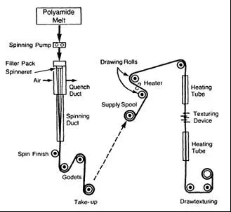
An example of the set-DTY process is illustrated by Fig.7. The figure shows the melt-spinning of nylon POY, which is then transferred to the draw texturing process. Here, the yarn is first drawn with a draw ratio of the order of 2.3 to 3.5 at a temperature of at least 50℃ ( Tg = 40oC), then subjected to simultaneously false twisting (friction disc device) , heating and a further drawing zone with a draw ratio of from 1.1 to 1.5. After the false twisting, the DTY passes through the additional heating zone to become a set-DTY. The process is particularly useful for the manufacture of nylon textured yarns having a linear density in the range of from about 10 dtex to about 50 dtex [72]
Generally all thermoplastic multifilament yarns made from polyesters, nylons and polypropylene can be converted into DTYs. Polyester yarns are normally within the count range of 55.6 to 333tex (50 to 300 den), with the emphasis on 83.3 tex to 166.7 tex (75 to 150 den). Nylon yarns are in the range from 16.7 to 122.2 tex (15-110 den); Polypropylene yarns are typically 7.7 to 100tex (70 – 900den) [ 73][74]
Despite the fact that false-Twist? texturing gives CF yarns a more natural feel bulk and stretch, their uniform geometry lacks the natural appearance of staple-spun yarns. Various techniques have been developed, therefore, to modify their appearance. An additional drawing zone using a hot-pin may be placed before the texturing stage, and used to impart irregular and repetitive changes to the filaments, so that after texturing the yarns display light and dark sections when dyed. If in the main drawing stage, the draw ratio is cyclically varied from high to low, while the Twist? insertion is similarly varied, the textured yarn will have thick and thin places along its length. Although some of these features may be removed during downstream processing, sufficient are retained to give an enhanced textured appearance in the subsequent woven or knitted fabric.
Fig.7 Illustration of the set-DTY process
Air-Jet Texturing
Although false-Twist? draw texturing is the most widely used method for converting flat thermoplastic CF yarns to ones of more bulky structures, air-jet texturing has become increasingly important because of it capability to process CF yarns of any polymer type, not just thermoplastics, and also glass filaments. For example cellulosic rayon which is not a thermoplastic, can be air-jet textured and air-jet textured E-glass is widely used for technical applications. Air-jet texturing can be used to process FDY/FOY (to give an air- textured yarn – ATY) or with a pre-drawing stage in an integrated draw-texturing system to convert POY to a drawn-air textured yarn – DATY)
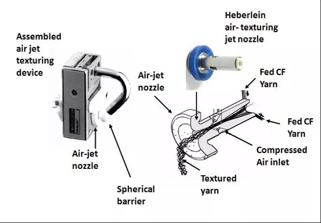
Various air-jet designs may be used to make ATY and DATY; Fig.8 illustrates one of the widely used jets, referred to as an axial-jet (venturi jet). Basically, the Filament?lengths to be textured are fed without tension into the jet ; this is achieved by ensuring that the speed at which they are fed into the jet is faster than the speed at which they leave the jet, the compressed air entering the jet can then act on the loose Filament?lengths. A ratio > 1, of input to output speed is termed the overfeed. With an axial jet, the compressed air is accelerated to the outlet while dragging the filaments along. A spherical barrier is positioned close to the outlet orifice, so that as the compressed air exits it becomes a turbulent air flow. The Filament? lengths in the turbulent flow initially become separated, forming a profusion of loops of various sizes. These entangle as the filaments get pulled together by removal rollers, to deliver an air- textured CF yarn.
A vortex –jet design can also be used. In this device the compressed air has a spiralling turbulent flow to the outlet, the loose Filament? lengths would become separated, and would form a profusion of different sizes of entangled loops as they exit the jet to become the ATY. Usually jets operate at pressures of about 10 bar (140 psi) and the actual texturing occurs directly at the exit of the jet in what is a turbulent supersonic air stream. To assist the loop formation, the filaments are wetted prior to entering the jet, by either Spraying? or dipping the yarn into a water bath; the water aids separation of the filaments and acts as a Lubricant? inside the jet. See Fig 9.
Fig 8 Air-jet Texturing Device
POY are preferred for air jet textured yarns largely because they are less expensive than FOY. The operating stages of the DATY machine (Fig.9) would therefore be of a similar configuration to the DTY machine, but with the false-twisting device replaced by the air-jet system. There are basically 2 types of yarns which can be produced with air texturing. The first type is called parallel yarns and the second type core effect yarns, and Fig.9 illustrates the production of both. The production of parallel yarns involves one or more POY being fed into the air jet device with precisely the same overfeed for all the yarns used. Usually 18% to 30% overfeed may be applied, depending on end-use requirements; parallel yarns are commonly used cut pile plush fabrics.
Core effect yarns are produced with two main components; core and the effect yarns. Both may be comprised of one or more POY. The overfeed used for the core yarn(s) is always lower than that for the effect yarn(s); the former, normally between 5 – 15% whereas the latter can be up to 400%, again depending on the end-use. For example, overfeeds of 8% core and 40% effect would be used for an apparel end-use such as nylon sportswear; while 120% effect yarn overfeed would be appropriate for upholstery fabrics, both domestic and car seat upholstery.
Fig. 9 Processes for Parallel and Core Effect ATY
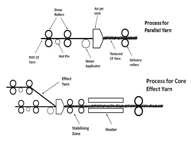
In Fig32, the drawing zones for both yarn types have a heating element, which may be a heated pin, godet or plate. The heating element is essential for polyester POY, but nylon and polypropylene POY may be cold drawn. Note that in the case of core effect type yarns, the two yarn paths must have their own drawing zone and therefore heating element. Although CF yarns of virtually any polymer can be air-jet textured, the number of filaments and the dtex/denier per Filament? are very important; a high number of filaments with a low detex/denier per Filament? being preferred. Rarely are yarns with a higher than 3.3dtex (3 denier) per Filament? air-jet textured. Currently, the practice is to use between 1.1 and 2.2 detex (1 and 2 denier) per Filament? {dpf}, the most popular yarns being more towards 1dpf or finer.
Air consumption is one significant cost factor in the process which must be kept as low as possible. Therefore a variety of air-texturing jets are available to cover the different ranges of dpf. Generally, vortex type jets are used for products which require less than 100% overfeed, whereas the venturi type of jet can be used with overfeeds of up to several hundred per cent. Loop size and loop stability are important factors, especially for finer detex/denier yarns. Smaller loops are more stable and give a better bulkiness than larger loops. As Fig.32 shows, on leaving the air-jet, the textured yarn can be heat treated to increase the stability and shrink the loops into a smaller size,. The temperatures must be hot enough to ensure that the yarns are adequately treated. The usual setting temperatures are 230 – 240 °C for finer polyester yarns. If required, an additional drawing zone placed between the air-jet and the heater can also be used to ensure smaller size loops are obtained.
A further addition to the process line can be made, used to convert the small loops into hairs, thereby simulating the structure of staple spun yarns which have short protrusions of fibre ends from the yarn’s surface. The process used for achieving this staple-fibre like yarn is called “Texspun” developed by the machine manufacturer Barmag [75]. The Texspun device is located in the heat stabilizing zone, so that as the yarn passes through the device the loops are torn and free fibre ends, very similar to staple fibre, are produced.
Bulk Continuous Filament? (BCF) Technology
The major application for BCF yarns is tufted carpets, but the technology has been developed to run at higher speeds and produce finer counts which enables BCF yarns to enter the textile and apparel sectors such as furnishings and outerwear. Nylon (PA & PA6.6) of 600dtex, 3.3 – 5.6. dtex (3 -5 den) filaments (compared with 11.1-16.7 /10-15 dpf) can be produced at productions speeds of up to 3500 m/min. Molecular weight and molecular weight distribution currently limit PP-BCF yarns to 900dtex and 3000 m/min. PET requires a long time for heat transfer to the core of the filaments and further development work is needed, for PET-BCF yarns to become available.


Comments are closed.